

Abstract: Radial thrust sliding bearings bear the radial force and axial thrust of the rotor respectively. This article focuses on the design improvement of a typical radial thrust sliding bearing structure, making the improved bearing structure convenient for maintenance and reducing maintenance costs. It also comprehensively analyzes the manufacturing process of key bearing components after the design improvement, summarizes practical and feasible processing solutions, and solves technological problems, which has good economic benefits in reality.
Keywords: design improvement; Cost; workmanship economic benefits
1. Introduction
Sliding bearing has the advantages of smooth operation, no noise, small radial size, impact resistance and large load capacity, so it has been widely used in Rotor machine. The existing typical gearbox radial thrust bearing mainly includes a bearing housing, oil seal, and radial tilting pad. A limited screw hole is set on the bearing shell, and the radial tilting pad is located at this hole. The main thrust bearing surface and the auxiliary thrust bearing surface are integrated on the axial two ends of the bearing shell. The radial tilting pad, main thrust bearing surface, and auxiliary thrust bearing surface are the main supporting parts for the radial force and axial thrust of the rotor, respectively. They are vulnerable parts. The bearing alloy on the bearing surface may be damaged and ineffective after a certain service life, or even before reaching the expected life, due to factors such as insufficient lubricant and impurities in the lubricant. Therefore, a new bearing needs to be replaced.
The radial thrust bearing of this structure needs to be replaced as a complete set when replacing a new bearing. However, the process of replacing the complete set of bearings is cumbersome and expensive, and it can be directly replaced when most components are still usable, resulting in resource waste and high maintenance costs.
2. Design improvement and significance
2.1 Design Improvement
By analyzing the structure of the radial thrust bearing, the integrated main thrust bearing surface and auxiliary thrust bearing surface are separated from the bearing shell as independent main thrust bearings and auxiliary thrust bearings, and positioning grooves and pins are machined on the two axial end faces of the bearing shell. The main thrust bearing and auxiliary thrust bearing include the disc substrate and the thrust bearing surface cast with bearing alloy on the surface. The disc substrate is made of different materials such as copper alloy and carbon steel according to actual working conditions. Multiple conical positioning holes are installed in the circular positioning grooves on the axial end faces of the bearing shell, and the main thrust bearing and auxiliary thrust bearing are respectively installed on the axial end faces of the bearing shell, as shown in Figure 1.
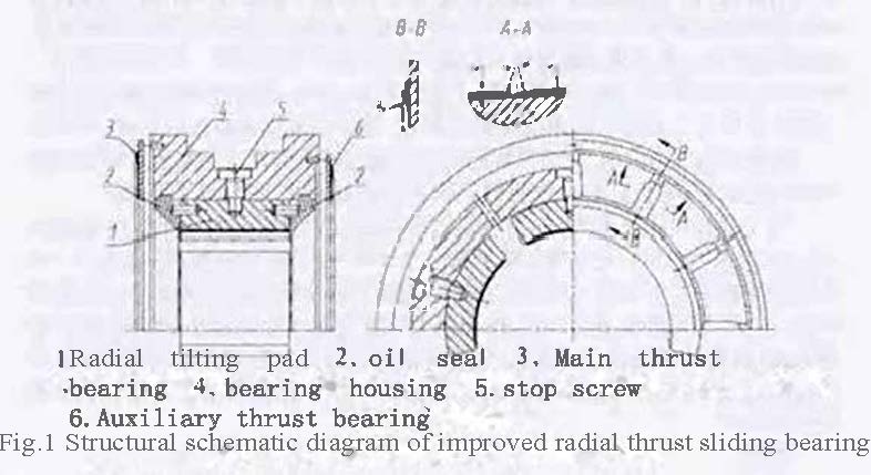
The bearing surfaces of the main thrust bearing and the auxiliary thrust bearing are equipped with arc-shaped oil inlet grooves and arc-shaped oil discharge grooves, which are processed with a spherical end milling cutter, as shown in Figure 1. The radius of the oil inlet groove is equal to the radius of the oil outlet groove, and the connection between the oil inlet groove and the oil outlet groove is also in a circular arc shape. The radius of this circular arc is equal to the radius of the oil inlet groove.
2.2 Improvement significance
By adopting the above structural improvement plan, the layout of the entire bearing is made more reasonable. In the case of severe wear and failure of radial tilting pads, main thrust bearings, and auxiliary thrust bearings, the maintenance of the entire bearing can be completed by simply replacing the corresponding components. The connection method of this structure is simple, reliable, and easy to disassemble, which can greatly reduce maintenance costs.
The flat bottom oil inlet and outlet grooves set on the integrated main thrust bearing surface and auxiliary thrust bearing surface have been improved into circular grooves, making the oil inlet and outlet on the bearing surface of the main thrust bearing and auxiliary thrust bearing smoother, facilitating the formation of oil film, reducing power consumption, improving lubrication effect, and slowing down wear between various components. And both the oil inlet and outlet grooves are circular in shape, which can reduce the stress concentration of the main thrust bearing and the auxiliary thrust bearing, and reduce deformation caused by machining.
3. Process Analysis and Design
3.1 Process Analysis
In the manufacturing industry, parts with a thickness to diameter ratio exceeding 1:50 are called thin sheet parts, and the main thrust bearings and auxiliary thrust bearings mentioned above are typical thin sheet parts. Thin plate parts have poor rigidity and weak strength, and are prone to deformation during processing, making it difficult to ensure the machining quality of the parts. This is a challenging problem in machining, and there are three main factors that affect the machining accuracy of thin plate parts:
(1) The workpiece is prone to deformation under force. Due to the thin wall of the workpiece, it is easy to deform under the clamping force, which affects the dimensional and shape accuracy of the workpiece;
(2) The workpiece is prone to deformation due to heat. Due to the thin thickness of the workpiece, cutting heat can cause thermal deformation of the workpiece, making it difficult to control the accuracy of the workpiece;
(3) The workpiece is prone to vibration and deformation. Under the action of cutting force, it is easy to generate vibration and deformation, which affects the dimensional accuracy, shape, position accuracy, and surface roughness of the workpiece.
3.2 Process Design
We comprehensively consider factors that affect the machining accuracy of thin plate parts, such as workpiece clamping, process settings, tool geometric parameters, and program development, to effectively improve the accuracy of the parts and ensure product quality.
(1) Use a mandrel to clamp the workpiece. The spindle clamping changes the radial force that mainly causes deformation of the workpiece into axial force, which can reduce the clamping deformation of the workpiece. Leave clamping process allowance in the inner hole of the workpiece, and clamp the core shaft within the clamping process allowance range. When turning one side, add a baffle with a buffer pad on the other side to improve the rigidity of the workpiece, reduce vibration caused by cutting force, and achieve simultaneous clamping of both sides of the workpiece, ensuring the parallelism of the two end faces of the workpiece.
(2) Add a semi precision machining and aging treatment process to both ends of the surface. After completing one semi precision machining of the workpiece, leave a margin on both ends to ensure that the entire plane can be polished. The margin is generally 0.05-0.10mm, and a second semi precision machining is carried out to eliminate plastic deformation caused by the secondary semi precision machining. Add an aging treatment process between two semi precision machining operations to eliminate the stress generated by cutting and clamping forces, as well as the residual stress of the part itself. Use tooling to clamp the two end faces, and smooth the plane of the clamping core shaft in the inner hole of the lathe to correct the flatness of the workpiece clamping plane and reduce the elastic deformation caused by the clamping force of the workpiece.
(3) Choose a reasonable tool angle and cutting amount. Due to the blunt cutting tool, it can cause deformation of the workpiece towards the cutting force direction, and the surface roughness of the workpiece is not easily guaranteed. The tool is too sharp, which can achieve micro cutting, but it will also pull the workpiece towards the opposite direction of the axial cutting force, causing deformation.
After multiple practices, the reasonable angle for tool Z is the main rake angle of 25 °~30 °, the main rake angle of 5 °~10 °, the main declination angle of 91 °~95 °, the secondary declination angle of 5 °~8 °, and the blade inclination angle of 0 °~3 °. The tool tip is deburred with an oilstone.
During precision machining, the tool feed is 0.05-0.08mm/r, the back feed is 0.04-0.07mm, and the cutting speed is around 60m/min. It is recommended that the workpiece does not vibrate. The constant linear speed G96 command of the CNC lathe can be used to change the speed by calculating the position of the tool from the center of the workpiece, so that the instantaneous position of the workpiece and the cutting edge maintain a constant speed, ensuring the surface roughness value of the workpiece.
(4) When turning on Cutting fluid during processing, emulsion is generally used. Cutting fluid can effectively solve the cutting heat generated during the cutting process, ensure the accuracy of the parts, and play a lubricating role, extending the service life of the tool and improving cutting efficiency.
4. Conclusion
After the structural design improvement of radial thrust sliding bearings, the layout is reasonable, the performance is reliable, and maintenance is more convenient. This technical improvement plan can also be applied to the design and transformation of other types of sliding bearings. By analyzing the factors that affect the machining accuracy of thin plate parts, specific methods for solving key processes have been summarized. Through practice, it has been proven that the above processes are scientific, the product quality is reliable, and can meet the needs of mass production.
More about Epen E92 Bushing:
E92 is deriving from E90; the difference between E90 & E92 is Indentations on working surface, which substituted by throughholes. Theses holes will allow greater capacity to collect lubricant, which build up a lubrication film at the start of movement and reduce the frication. It is suitable for high load, lower speed application like construction, transport, and agriculture machinery.
https://www.cnepen.cn/showinfo-217-560-0.html

